FOB Price
Get Latest Price|
- Minimum Order
Country:
China
Model No:
ST8062
FOB Price:
Place of Origin:
-
Price for Minimum Order:
-
Minimum Order Quantity:
-
Packaging Detail:
-
Delivery Time:
-
Supplying Ability:
-
Payment Type:
T/T
Product Group :

China
Contact Person Mr. Gordon
Floor 2, Building F, Guangzhou, Guangdong
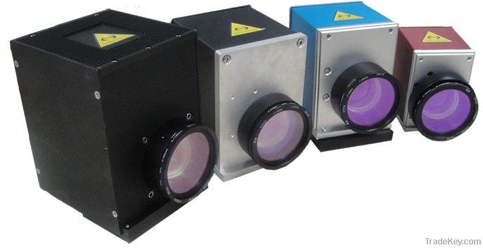
Laser Marking Heads (Laser Scanners, Optical Scanners, Scan Heads)
A whole laser marking head (or called laser scanner) consists of two scan mirrors, two galvanometers (or called galvo-scanner motor) & drive cards, a XY mount, a scanning lens (f-theta lens), an interface card (or called D/A card), a set of marking software and a DC power supply. Two types of scanning optics for CO2 and Nd:YAG lasers are available.
Basics of *-axis laser scanners
|
A laser beam is reflected from two scan mirrors in turn, and directed through a focusing lens. The mirrors are capable of high speed deflection about a rotation axis, being driven by a galvo-scanner motor. In most cases the maximum deflection angle of the mirror is ±*2.5° (often ±*0° is a safer limit) either side of the non-deflected incidence angle of *5°. Note that, for best performance, the lens will appear to be ‘the wrong way round’ when compared with a standard meniscus lens used in conventional focusing of a laser beam. Some of the design objectives in
specification of *-axis laser scanners are: Some of the limitations to be
considered are: |
|
Field of scan
The laser beam will be scanned over an angle q, equal to twice the mirror deflection angle. So, the typical scanned field might be q=±*0° in both X and Y directions. (q=±*5° would be the usual maximum scanned field). The field size is then approximately 2Ftanq? in both X and Y.
The approximation arises because:
1) it is usually desirable to have
a deliberate distortion characteristic in the scanner lens design
so that the field position is proportional to q, not tanq.
2) scanning in two axes produces a geometrical distortion which is
unrelated to the lens properties.
Focused spot size
The lower limit on spot size ‘d’ (1/e2 intensity diameter) for a laser beam of diameter ‘D’ (1/e2) is:
d = *3.5QF/D mm
Example: A TEM*0 beam (Q=1) of *3.5mm (1/e2) diameter, focused by a perfect lens of **0mm focal length, will form a focused spot of **0mm diameter. (Taking a more realistic value of Q=1.5, the spot size would be **0mm).
Beam clipping and optical aberrations can lead to focused spot sizes which are larger than the minimum diffraction limited value found from the equation above.
Large field sizes demand the use of lenses of long focal length. In turn, this leads to increased focused spot size unless the beam diameter, mirror sizes, and lens diameter are all increased.
| Country: | China |
| Model No: | ST8062 |
| FOB Price: | Get Latest Price |
| Place of Origin: | - |
| Price for Minimum Order: | - |
| Minimum Order Quantity: | - |
| Packaging Detail: | - |
| Delivery Time: | - |
| Supplying Ability: | - |
| Payment Type: | T/T |
| Product Group : | lasers and laser components |