FOB Price
Get Latest Price|
- Minimum Order
Country:
China
Model No:
-
FOB Price:
Place of Origin:
-
Price for Minimum Order:
-
Minimum Order Quantity:
-
Packaging Detail:
-
Delivery Time:
-
Supplying Ability:
-
Payment Type:
-
Product Group :

China
Contact Person Mr. Wilson
6-703, FUYUAN COMMUNITY, YUFU ROAD, LONGGANG DISTRICT, SHENZHEN, CHINA, Muping, Sichuan
New
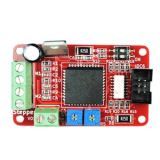
Version Stepper Motor Driver Shield V1.0 -Arduino
Compatible
The stepper motor is the open loop control
element that can change the electrical pulse signal into angular
displacement or linear displacement. Under non-overload conditions,
the motor speed, the stop position only depends on the frequency
and number of pulses of the pulse signal, and regardless of load
changes, its rotation is operated in a fixed angle step by step. We
can control the amount of angular displacement through controlling
the number of pulses, so as to achieve accurate positioning
purposes; At the same time we can also control the speed rotation
and acceleration of the motor through controlling the pulse
frequency, then to achieve speed adjustment.
The main
controller chipset for stepper motor module V1.0 is
A***7.
First: Connect with external power supply through
V*1 interface, the voltage of this module should be between
8.0V and *5V.
Second: The interface contains reset
control and other three way control signal. About the stepper motor
output, One of phase coil of the dual phase stepper motor is
connected to M1A and M1B, another phase coil is connected to the
M2A and M2B. D
Please adjust the precision of the stepper
motor through the switch 1 and switch 2 as follows:
1,
Step Precision Choice
2, The Current Maximum
Choice
The user can change the size of the current of
stepper motor by changing the size of R5 resistance. When clockwise
rotation R5, the current increase. More current means a strong
drive ability and more power consumption and emit more
heat.
3, PFD Voltage
Please adjust the voltage of
PFD through R4, which is to control the current attenuation mode.
If PFD voltage is higher than 0.6 VDD, then choose slow
attenuation mode; If Less than 0.*1 VDD, then choose fast
attenuation mode; If between the two mode, then choose mixed
attenuation mode.
Different speed of the motor should
choose different attenuation mode. High speed for fast attenuation,
low speed for slow attenuation. When high speed for slow
attenuation will appear vibration with high noise. Low speed for
fast attenuation will lead to serious motor weakness, if very
serious then will appear the phenomenon of positioning is not
exact.
4, Power
Stepper motor module
working voltage range: DC 8.***5V.
5, Output
Connection
One of phase coil of the dual phase stepper
motor is connected to M1A and M1B, another phase coil is connected
to the M2A and M2B. Different stepper motor may have different
connection.
In addition, this module adopt a TLP****4
optical coupler, which has strong anti-jamming ability, work
stability, long service life and higher transmission
efficiency...etc characteristic, the most important thing is to
realize the complete electrical isolation between port and
output port.
| Country: | China |
| Model No: | - |
| FOB Price: | Get Latest Price |
| Place of Origin: | - |
| Price for Minimum Order: | - |
| Minimum Order Quantity: | - |
| Packaging Detail: | - |
| Delivery Time: | - |
| Supplying Ability: | - |
| Payment Type: | - |
| Product Group : | arduino board and accessories |


")


